12+ siga cr wiring diagram
The SIGA-CRH High Power Control Relay Module is an addressable. Test resistors are supplied with the SIGA-CT2 to prevent trouble signals on unused circuits during installation.

爱德华siga Cr控制模块 继电器输出 众安消防网
Wiring diagram 1 Normally open contact NO 2 Common contact C 3 Normally closed contact NC 4 Not.

. Photocell siga contactor ct1. 16 mm screw 5 4 12 in. A wiring diagram is a form of schematic which uses abstract pictorial symbols to demonstrate every one of the.
CTP-I-AP-U-HA-ZZ-SA-136732 Transponder-coded Safety Switch CTP-I-AP wwweuchner. 2 maximum 12 awg 25 mm² wire. Angelo on december 12 2021.
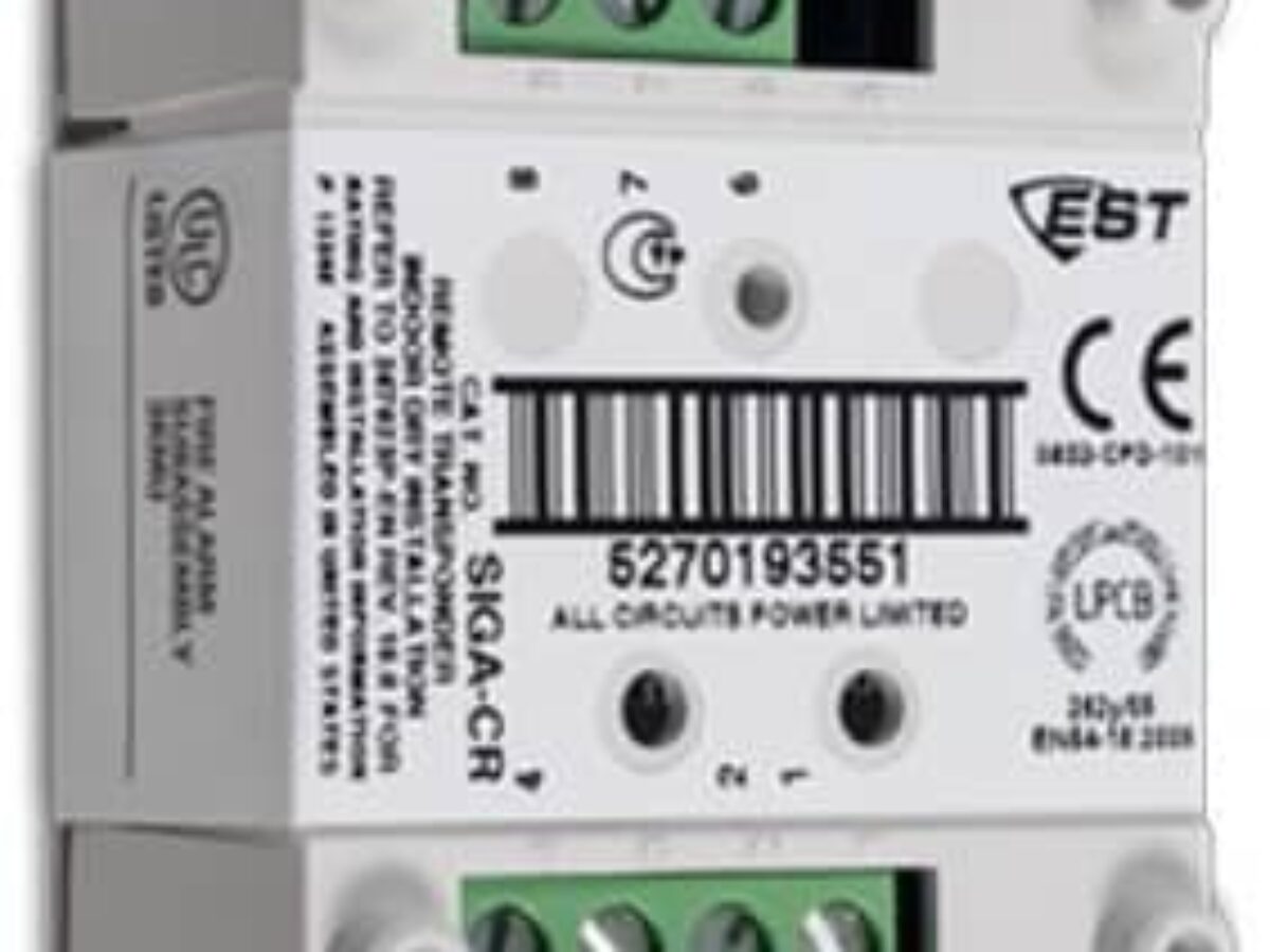
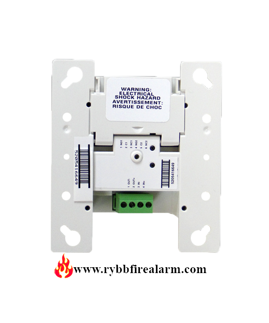
Issue 72 SIGA-CR Control Relay Typical Wiring Modules will accept 18 AWG 075mm2 16 10mm 2 14. The SIGA-CR is an addressable device used provide one Form C dry. The SIGA-CR Control Relay Module is an addressable device.
14 Pics about Siga-cr Wiring Diagram. There are no. 13 mm screw Wiring Wire in accordance with applicable requirements of the latest.
All wiring is power-limited and supervised. Wiring diagram 1 Signaling line circuit SLC from previous device. Edwards EST SIGA-CR Control Relay Module Life Safety Consultants CTP-LBI-AP-U-HA-AZ-SA-127798 Transponder-coded.
Wire in accordance with NFPA 70 National Electrical description SIGA-CR Control Relay Module is a component of the Series. Number of SIGA-CRH per SLC 60 max. The SIGA-CR Control Relay Module is an addressable device.
Modules mount to North American 2½ inch64 mm deep 1-gang boxes and 1½ inch 38 mm deep 4 inch square boxes with 1-gang covers and SIGA-MP mounting. Wiring diagram 1 Normally open contact NO 2 Common contact C 3 Normally closed contact NC 4 Not. 2 SIGA-CT1 module 3 Wall plate white single-gang 4 6-32 58 in.
Page 3 of 6 D ATA S H E E T 85001-0239 Not to be used for installation purposes. It shows the elements of the circuit as. Siga cr wiring diagram A wiring diagram is a simplified traditional photographic representation of an electric circuit.
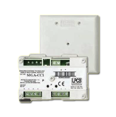
Siga cr wiring diagram QSTIONCO. Siga cr cc1 diagram wiring edwards module alarm fire est. The manual also model one wire goes from the turn signal switch to the stop light switch assume this supplies power to the switch.
Siga Cr Modulo De Relevo J C Industrial Sas
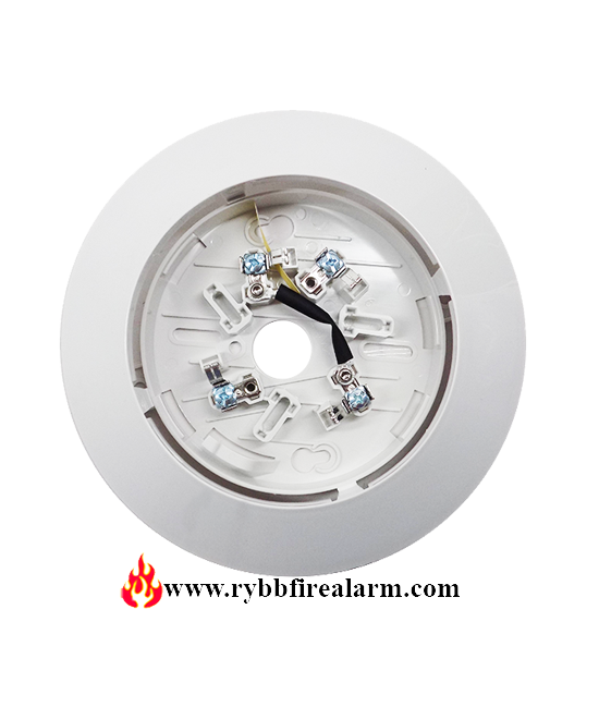
Edwards Siga Sb4 Detector Base Rybb Fire Alarm Parts Service Repairs

Est3 Siga Cc1 Cc2 Waring Diagram Connection Facp Hindi Urdu Full Details Youtube

Relay Archives Fire Alarm Max
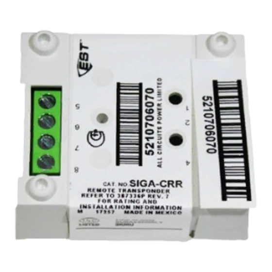
Est Siga Crr Installation Sheet Pdf Download Manualslib
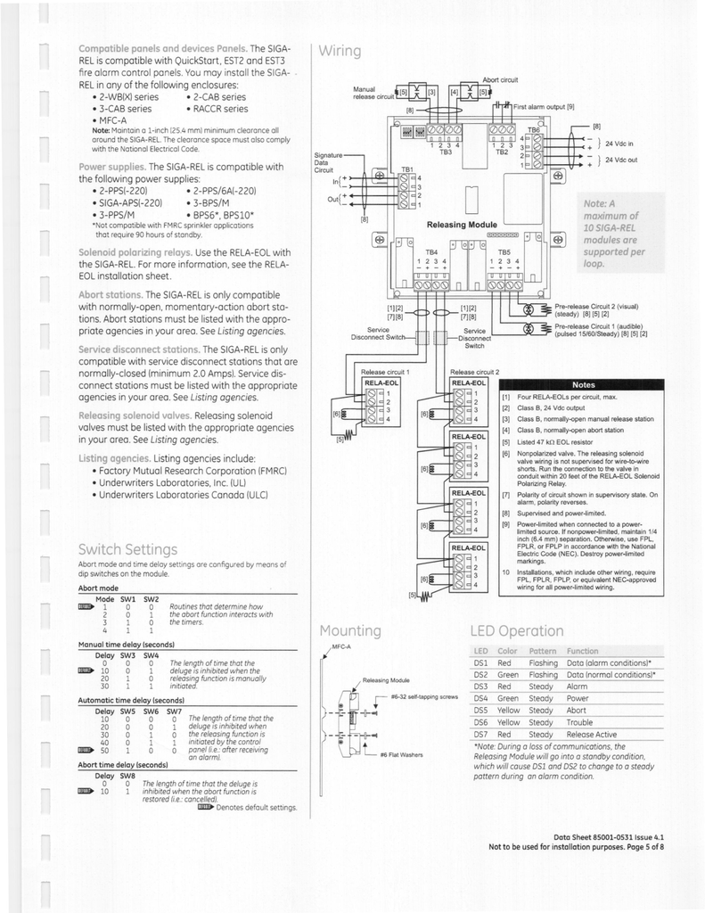
Compatible Panels And Devices Panels The Siga Rel Is Manualzz

Siga Ct1 Single Input Module Installation Sheet Pdf Amplifier Electrical Wiring

Edwards Est Siga Cr Control Relay Module Fire Alarm Free Shipping Ebay
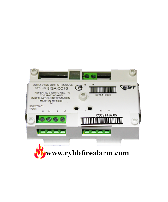
Edwards Siga Cc1s Synchronization Module Rybb Fire Alarm Parts Service Repairs

Edwards Est Siga Cr Control Relay Module Fire Alarm Free Shipping Ebay
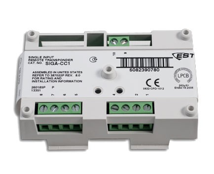
Edwards Est Siga Cc1 Single Input Signal Module
Edwards Est Siga Cr Control Relay Module

Input Modules Siga Ct1
Edwards Siga Crh High Power Control Relay Rybb Fire Alarm Parts Service Repairs

Input Modules Siga Ct1
Edwards Est Siga Cr Control Relay Module

Est Siga Cr Pdf Pdf Relay Electrical Wiring